
Introduction
Hello to all readers of the blog about IT Architecture and Education.
We continue publishing articles under the conceptual title “Architecture and Design. Implementation and Operation. Code and Programming”.
In the previous article, we talked about this concept in general and about creating an environment and setting up tools for developing code.
Today we’ll start writing code to display a Microsoft System Center Virtual Machine Manager 2007 system architecture diagram in Visio format for a related series of articles.
Microsoft Visio and PowerShell. First steps
So let’s start with simple steps.
Let’s create a Visio application object and a new document based on an empty template. Let’s set the active page, on which we will later programmatically draw our architectural scheme.
# Step 1.
# Create Visio Object
# Create Document from Blank Template
# Set Active Page
$Application = New-Object -ComObject Visio.Application
$Application.Visible = $True
$Documents = $Application.Documents
$Document=$Application.Documents.Add('')
$Page=$Application.ActivePage
$Application.ActivePage.PageSheet
We add stencils of basic figures (BASIC_M.vss). First we will need a rectangle template.
# Step 2.
# Add Basic Visio Stensils
# Set Masters Item Rectangle
$Stensil1 = $Application.Documents.Add("BASIC_M.vss")
$Rectangle = $Stensil1.Masters.Item("Rectangle")
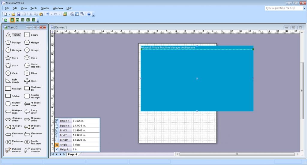
We draw a rectangle with color and the inscription “Microsoft Virtual Machine Manager Architecture”. We align the text along the upper edge of the rectangle and to the left. This figure will be the basis of our scheme. To aesthetically emphasize the inscription, draw a line of the appropriate color under it.
# Step 3.
# Draw Main Rectangle, Set Size, Set Colour
# Set Text, Size, Color, Align
# Draw Line, Set Weight, Color
$Shape1 = $Page.Drop($Rectangle, 6.375, 7.125)
$Shape1.Cells('Width').Formula = '12.2501'
$Shape1.Cells('Height').Formula = '7.25'
$Shape1.Cells('FillForegnd').Formula = '=RGB(0,153,204)'
$Shape1.Cells('LinePattern').Formula = 0
$Shape1.Text = "Microsoft Virtual Machine Manager Architecture"
$Shape1.Cells('VerticalAlign') = 0
$Shape1.Cells('Para.HorzAlign') = 0
$Shape1.Cells('Char.Size').Formula = '20 pt'
$Shape1.Cells('Char.Color').Formula = '=RGB(255,255,255)'
$Line1 = $Page.DrawLine(0.3125, 10.3438, 12.4948, 10.3438)
$Line1.Cells('LineWeight').Formula = '1 pt'
$Line1.Cells('LineColor').Formula = '=RGB(255,255,255)'
The intermediate result of the previous steps looks like this:
Similarly, draw a rectangle that will display the client system.
# Step 4.
# Draw Client Rectangle, Set Size, Set Colour
# Set Text, Align
# Draw Line
$Shape2 = $Page.Drop($Rectangle, 1.7656, 9.2344)
$Shape2.Cells('Width').Formula = '2.7813'
$Shape2.Cells('Height').Formula = '1.9688'
$Shape2.Cells('FillForegnd').Formula = '=RGB(209,235,241)'
$Shape2.Cells('LinePattern').Formula = 1
$Shape2.Text = "Client"
$Shape2.Cells('VerticalAlign') = 0
$Shape2.Cells('Char.Size').Formula = '14 pt'
$Line2 = $Page.DrawLine(0.4297, 9.9427, 3.0833, 9.9427)
$Line2.Cells('LineWeight').Formula = '0.5 pt'
$Line2.Cells('LineColor').Formula = '=RGB(0,0,0)'
There will be several objects within this rectangle. We add stencils of computer-themed figures (COMPS_M.vss), and we will work with the Personal Computer “PC” icon template.
# Step 5.
# Add Computer Items Visio Stensils
# Set Masters item PC
$Stensil2 = $Application.Documents.Add("COMPS_M.vss")
$PC1 = $Stensil2.Masters.Item("PC")
We attach an image of a Personal Computer with the Signature “Administrator Console”.
# Step 6.
# Draw item PC
# Set Text, Size
$Shape3 = $Page.Drop($PC1, 1.1173, 9.1693)
$Shape3.Text = "Administrator Console"
$Shape3.Cells('Char.Size').Formula = '10 pt'
Add a Powershell icon. In this case, we will use a picture prepared in advance in PNG format (PowerShell.png).
# Step 7.
# Draw Powershell Icon
# Set Position, Size
# Set Text
$Picture1 = $Page.Import("c:\!\powershell.png")
$Picture1.Cells('Width').Formula = '0.9843'
$Picture1.Cells('Height').Formula = '0.9843'
$Picture1.Cells('PinX').Formula = '2.5547'
$Picture1.Cells('PinY').Formula = '9.2682'
$Picture1.Text = "Windows Powershell"
$Picture1.Cells('Char.Size').Formula = '10 pt'
We draw a rectangle that will display the software interface of communication between client systems and server systems – Windows Communication Foundation.
# Step 8.
# Draw WCF Rectangle, Set Size, Set Colour
# Set Text, Align
# Draw Line
$Shape4 = $Page.Drop($Rectangle, 4.2682, 6.9063)
$Shape4.Cells('Width').Formula = '1.5'
$Shape4.Cells('Height').Formula = '6.625'
$Shape4.Cells('FillForegnd').Formula = '=RGB(255,255,255)'
$Shape4.Cells('LinePattern').Formula = 1
$Shape4.Text = "Windows Communication Foundation"
$Shape4.Cells('VerticalAlign') = 0
$Shape4.Cells('Char.Size').Formula = '14 pt'
$Line3 = $Page.DrawLine(3.5664, 9.4063, 4.9492, 9.4063)
$Line3.Cells('LineWeight').Formula = '0.5 pt'
$Line3.Cells('LineColor').Formula = '=RGB(0,0,0)'
Add a WCF icon.
# Step 9.
# Draw WCF Icon
# Set Position, Size
$Picture2 = $Page.Import("c:\!\WCF.png")
$Picture2.Cells('Width').Formula = '1.412'
$Picture2.Cells('Height').Formula = '1.0443'
$Picture2.Cells('PinX').Formula = '4.2708'
$Picture2.Cells('PinY').Formula = '6.9779'
We connect two objects with a line – the Client System with the Windows Communication Foundation software interface. This will reflect two-way communication.
# Step 10.
# Draw Line communication from Client to WCF
# Set Arrow
$Line4 = $Page.DrawLine(3.1563, 9.2396, 3.5174, 9.2396)
$Line4.Cells('LineColor').Formula = '=RGB(255,255,255)'
$Line4.Cells('BeginArrow').Formula=4
$Line4.Cells('EndArrow').Formula=4
Add a rectangle that will display the web client.
# Step 11.
# Draw Web Client Rectangle, Set Size, Set Colour
# Set Text, Align
# Draw Line
$Shape5 = $Page.Drop($Rectangle, 1.7656, 6.8776)
$Shape5.Cells('Width').Formula = '2.7813'
$Shape5.Cells('Height').Formula = '2.1094'
$Shape5.Cells('FillForegnd').Formula = '=RGB(209,235,241)'
$Shape5.Cells('LinePattern').Formula = 1
$Shape5.Text = "Web Client"
$Shape5.Cells('VerticalAlign') = 0
$Shape5.Cells('Char.Size').Formula = '14 pt'
$Line5 = $Page.DrawLine(0.4297, 7.6562, 3.0833, 7.6562)
$Line5.Cells('LineWeight').Formula = '0.5 pt'
$Line5.Cells('LineColor').Formula = '=RGB(0,0,0)'
Similarly to the previous steps, we add the Self-Service Web Portal icon (SelfServicePortal.png) and another Powershell icon.
# Step 12.
# Draw Self Service Portal Icon
# Set Position, Size
# Set Text
$Picture3 = $Page.Import("c:\!\SelfServicePortal.png")
$Picture3.Cells('Width').Formula = '0.8438'
$Picture3.Cells('Height').Formula = '0.8438'
$Picture3.Cells('PinX').Formula = '1.1094'
$Picture3.Cells('PinY').Formula = '6.9271'
$Picture3.Text = "Self Service Portal"
$Picture3.Cells('Char.Size').Formula = '10 pt'
# Step 13.
# Draw Powershell Icon
# Set Position, Size
# Set Text
$Picture4 = $Page.Import("c:\!\powershell.png")
$Picture4.Cells('Width').Formula = '0.9843'
$Picture4.Cells('Height').Formula = '0.9843'
$Picture4.Cells('PinX').Formula = '2.4922'
$Picture4.Cells('PinY').Formula = '6.9192'
$Picture4.Text = "Windows Powershell"
$Picture4.Cells('Char.Size').Formula = '10 pt'Similarly, we again connect two objects with a line – the Web Client with the Windows Communication Foundation software interface. This will also reflect two-way communication.
# Step 14.
# Draw Line communication from Web Client to WCF
# Set Arrow
$Line6 = $Page.DrawLine(3.158, 6.8802, 3.5191, 6.8802)
$Line6.Cells('LineColor').Formula = '=RGB(255,255,255)'
$Line6.Cells('BeginArrow').Formula=4
$Line6.Cells('EndArrow').Formula=4
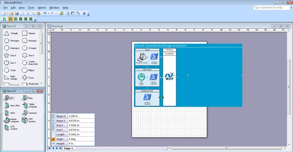
And the client picture is completed by a rectangle displaying client scripting with another Powershell icon. And, of course, we connect this object with the Windows Communication Foundation software interface by two-way communication.
# Step 15.
# Draw Scripting Client Rectangle, Set Size, Set Colour
# Set Text, Align
# Draw Line
$Shape6 = $Page.Drop($Rectangle, 1.7657, 4.5469)
$Shape6.Cells('Width').Formula = '2.7813'
$Shape6.Cells('Height').Formula = '1.9062'
$Shape6.Cells('FillForegnd').Formula = '=RGB(209,235,241)'
$Shape6.Cells('LinePattern').Formula = 1
$Shape6.Text = "Scripting Client"
$Shape6.Cells('VerticalAlign') = 0
$Shape6.Cells('Char.Size').Formula = '14 pt'
$Line7 = $Page.DrawLine(0.4297, 5.1979, 3.0834, 5.1979)
$Line7.Cells('LineWeight').Formula = '0.5 pt'
$Line7.Cells('LineColor').Formula = '=RGB(0,0,0)'
# Step 16.
# Draw Powershell Icon
# Set Position, Size
# Set Text
$Picture5 = $Page.Import("c:\!\powershell.png")
$Picture5.Cells('Width').Formula = '0.9843'
$Picture5.Cells('Height').Formula = '0.9843'
$Picture5.Cells('PinX').Formula = '1.7631'
$Picture5.Cells('PinY').Formula = '4.6015'
$Picture5.Text = "Windows Powershell"
$Picture5.Cells('Char.Size').Formula = '10 pt'# Step 17.
# Draw Line communication from Scripting Client to WCF
# Set Arrow
$Line8 = $Page.DrawLine(3.158, 4.5729, 3.5191, 4.5729)
$Line8.Cells('LineColor').Formula = '=RGB(255,255,255)'
$Line8.Cells('BeginArrow').Formula=4
$Line8.Cells('EndArrow').Formula=4The result of the previous steps looks like this:
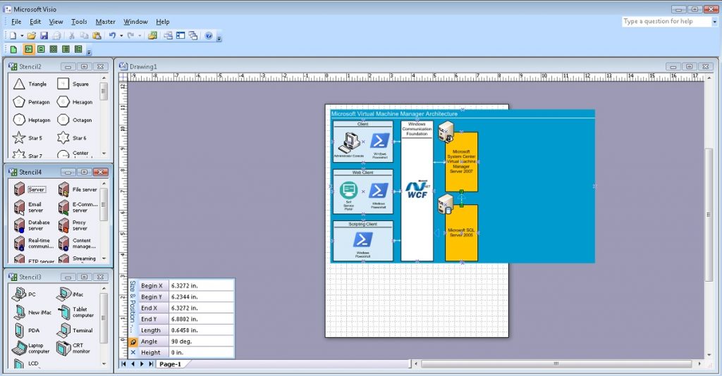
Now let’s move on to the main services. To visualize the work of the server part, we will use the stencils of figures of the corresponding topic (SERVER_M.vss), and we will work with the icon templates of the Management Server “Management server” and the Database Server “Database server”. First, we draw a rectangle for visualization of Microsoft System Center Virtual Machine Manager Server 2007 and, accordingly, another one for Microsoft SQL Server 2005. We place the corresponding server icons on top of the rectangles on the upper left. And of course, we connect the “Microsoft System Center Virtual Machine Manager Server 2007” object with the Windows Communication Foundation software interface by two-way communication, and with Microsoft SQL Server 2005 by one-way communication.
# Step 18.
# Draw Microsoft System Center
# Virtual Machine Manager Server 2007 Rectangle
# Set Size, Set Colour
# Set Text, Align
$Shape7 = $Page.Drop($Rectangle, 6.3281, 8.2812)
$Shape7.Cells('Width').Formula = '1.5'
$Shape7.Cells('Height').Formula = '2.8125'
$Shape7.Cells('FillForegnd').Formula = '=RGB(255,192,0)'
$Shape7.Cells('LinePattern').Formula = 1
$Shape7.Text = "Microsoft System Center Virtual Machine Manager Server 2007"
$Shape7.Cells('Char.Size').Formula = '14 pt'
# Step 19.
# Draw Microsoft SQL Server 2005 Rectangle
# Set Size, Set Colour
# Set Text, Align
$Shape8 = $Page.Drop($Rectangle, 6.3281, 4.9219)
$Shape8.Cells('Width').Formula = '1.5'
$Shape8.Cells('Height').Formula = '2.6563'
$Shape8.Cells('FillForegnd').Formula = '=RGB(255,192,0)'
$Shape8.Cells('LinePattern').Formula = 1
$Shape8.Text = "Microsoft SQL Server 2005"
$Shape8.Cells('Char.Size').Formula = '14 pt'# Step 20.
# Add Server Items Visio Stensils
# Set Masters item Management Server and Database Server
$Stensil3 = $Application.Documents.Add("SERVER_M.vss")
$MS1 = $Stensil3.Masters.Item("Management server")
$DBS1 = $Stensil3.Masters.Item("Database server")# Step 21.
# Draw item Management Server
$Shape9 = $Page.Drop($MS1, 5.6043, 9.7421)# Step 22.
# Draw item Management Server
$Shape10 = $Page.Drop($DBS1, 5.5832, 6.3046)# Step 23.
# Draw Line communication from WCF to Microsoft System Center
# Virtual Machine Manager Server 2007
# Set Arrow
$Line9 = $Page.DrawLine(5.0052, 8.2604, 5.6024, 8.2604)
$Line9.Cells('LineColor').Formula = '=RGB(255,255,255)'
$Line9.Cells('BeginArrow').Formula=4
$Line9.Cells('EndArrow').Formula=4# Step 24.
# Draw Line communication from Microsoft System Center
# Virtual Machine Manager Server 2007 to Microsoft SQL Server 2005
# Set Arrow
$Line10 = $Page.DrawLine(6.3272, 6.2344, 6.3272, 6.8802)
$Line10.Cells('LineColor').Formula = '=RGB(255,255,255)'
$Line10.Cells('BeginArrow').Formula=4
$Line10.Cells('EndArrow').Formula=0The result of the previous steps looks like this:
Microsoft System Center Virtual Machine Manager Server 2007 interacts with agent systems using Windows Remote Managemet (Win-RM) technology. So, let’s draw this component of the architecture in the same way as we drew the display of the Windows Communication Foundation software interface. And let’s connect this component with the Microsoft System Center Virtual Machine Manager Server 2007 object by two-way communication.
# Step 25.
# Draw Win-RM Rectangle, Set Size, Set Colour
# Set Text, Align
# Draw Line
$Shape11 = $Page.Drop($Rectangle, 8.4375, 6.9219)
$Shape11.Cells('Width').Formula = '1.5'
$Shape11.Cells('Height').Formula = '6.6563'
$Shape11.Cells('FillForegnd').Formula = '=RGB(255,255,255)'
$Shape11.Cells('LinePattern').Formula = 1
$Shape11.Text = "Windows Remote Managemet (Win-RM)"
$Shape11.Cells('VerticalAlign') = 0
$Shape11.Cells('Char.Size').Formula = '14 pt'
$Line11 = $Page.DrawLine(7.75, 9.1875, 9.1328, 9.1875)
$Line11.Cells('LineWeight').Formula = '0.5 pt'
$Line11.Cells('LineColor').Formula = '=RGB(0,0,0)'
# Step 26.
# Draw Win-RM Icon
# Set Position, Size
$Picture6 = $Page.Import("c:\!\Win-RM.png")
$Picture6.Cells('Width').Formula = '1.1563'
$Picture6.Cells('Height').Formula = '1.1563'
$Picture6.Cells('PinX').Formula = '8.4293'
$Picture6.Cells('PinY').Formula = '7'# Step 27.
# Draw Line communication from Win-RM to Microsoft System Center
# Virtual Machine Manager Server 2007
# Set Arrow
$Line12 = $Page.DrawLine(7.0781, 8.2812, 7.6753, 8.2812)
$Line12.Cells('LineColor').Formula = '=RGB(255,255,255)'
$Line12.Cells('BeginArrow').Formula=4
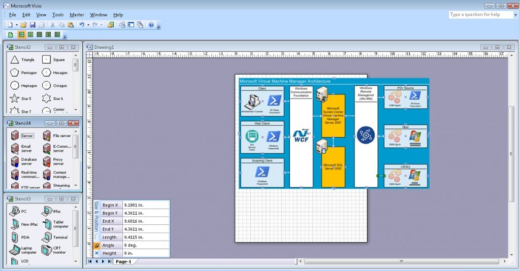
$Line12.Cells('EndArrow').Formula=4Interaction with Virtualization Hosts, Library, etc. is based on VMM Agent. Let’s begin to display these components of the architecture by visualizing the interaction of the processes of migration of services from a physical environment to a virtual one: P2V Source. We will need a rectangle, a line, VMM Agent and Powershell icons. And, of course, display two-way communication with Windows Remote Managemet (Win-RM) technology.
# Step 28.
# Draw P2V Source Rectangle, Set Size, Set Colour
# Set Text, Align
# Draw Line
$Shape12 = $Page.Drop($Rectangle, 10.9844, 9.5)
$Shape12.Cells('Width').Formula = '2.7813'
$Shape12.Cells('Height').Formula = '1.5'
$Shape12.Cells('FillForegnd').Formula = '=RGB(209,235,241)'
$Shape12.Cells('LinePattern').Formula = 1
$Shape12.Text = "P2V Source"
$Shape12.Cells('VerticalAlign') = 0
$Shape12.Cells('Char.Size').Formula = '14 pt'
$Line13 = $Page.DrawLine(9.6485, 9.9739, 12.3021, 9.9739)
$Line13.Cells('LineWeight').Formula = '0.5 pt'
$Line13.Cells('LineColor').Formula = '=RGB(0,0,0)'
# Step 29.
# Draw VMM Agent Icon
# Set Position, Size
# Set Text
$Picture7 = $Page.Import("c:\!\VMMAgent.png")
$Picture7.Cells('Width').Formula = '0.8438'
$Picture7.Cells('Height').Formula = '0.8438'
$Picture7.Cells('PinX').Formula = '10.2969'
$Picture7.Cells('PinY').Formula = '9.5'
$Picture7.Text = "VMM Agent"
$Picture7.Cells('Char.Size').Formula = '10 pt'# Step 30.
# Draw Powershell Icon
# Set Position, Size
# Set Text
$Picture8 = $Page.Import("c:\!\powershell.png")
$Picture8.Cells('Width').Formula = '0.7968'
$Picture8.Cells('Height').Formula = '0.7968'
$Picture8.Cells('PinX').Formula = '11.6016'
$Picture8.Cells('PinY').Formula = '9.6016'
$Picture8.Text = "Windows Powershell"
$Picture8.Cells('Char.Size').Formula = '10 pt'# Step 31.
# Draw Line communication from P2V Source to Win-RM
# Set Arrow
$Line14 = $Page.DrawLine(9.1875, 9.487, 9.599, 9.487)
$Line14.Cells('LineColor').Formula = '=RGB(255,255,255)'
$Line14.Cells('BeginArrow').Formula=4
$Line14.Cells('EndArrow').Formula=4Similarly, we display Virtualization hosts – Microsoft Virtual Server 2005 R2.
# Step 32.
# Draw Host Rectangle, Set Size, Set Colour
# Set Text, Align
# Draw Line
$Shape13 = $Page.Drop($Rectangle, 10.9792, 6.9427)
$Shape13.Cells('Width').Formula = '2.7813'
$Shape13.Cells('Height').Formula = '1.5'
$Shape13.Cells('FillForegnd').Formula = '=RGB(209,235,241)'
$Shape13.Cells('LinePattern').Formula = 1
$Shape13.Text = "Host"
$Shape13.Cells('VerticalAlign') = 0
$Shape13.Cells('Char.Size').Formula = '14 pt'
$Line15 = $Page.DrawLine(9.6472, 7.4219, 12.3008, 7.4219)
$Line15.Cells('LineWeight').Formula = '0.5 pt'
$Line15.Cells('LineColor').Formula = '=RGB(0,0,0)'
# Step 33.
# Draw VMM Agent Icon
# Set Position, Size
# Set Text
$Picture9 = $Page.Import("c:\!\VMMAgent.png")
$Picture9.Cells('Width').Formula = '0.8438'
$Picture9.Cells('Height').Formula = '0.8438'
$Picture9.Cells('PinX').Formula = '10.2917'
$Picture9.Cells('PinY').Formula = '6.9427'
$Picture9.Text = "VMM Agent"
$Picture9.Cells('Char.Size').Formula = '10 pt'# Step 34.
# Draw Microsoft Virtual Server 2005 R2 Icon
# Set Position, Size
# Set Text
$Picture10 = $Page.Import("c:\!\WS.jpg")
$Picture10.Cells('Width').Formula = '0.8125'
$Picture10.Cells('Height').Formula = '0.7404'
$Picture10.Cells('PinX').Formula = '11.5938'
$Picture10.Cells('PinY').Formula = '6.9423'
$Picture10.Text = "Microsoft Virtual Server 2005 R2"
$Picture10.Cells('Char.Size').Formula = '7 pt'# Step 35.
# Draw Line communication from Host to Win-RM
# Set Arrow
$Line16 = $Page.DrawLine(9.1849, 6.941, 9.5964, 6.941)
$Line16.Cells('LineColor').Formula = '=RGB(255,255,255)'
$Line16.Cells('BeginArrow').Formula=4
$Line16.Cells('EndArrow').Formula=4And similar to the previous steps, we display the elements of the Library.
# Step 36.
# Draw Library Rectangle, Set Size, Set Colour
# Set Text, Align
# Draw Line
$Shape14 = $Page.Drop($Rectangle, 10.9792, 4.3542)
$Shape14.Cells('Width').Formula = '2.7813'
$Shape14.Cells('Height').Formula = '1.5'
$Shape14.Cells('FillForegnd').Formula = '=RGB(209,235,241)'
$Shape14.Cells('LinePattern').Formula = 1
$Shape14.Text = "Library"
$Shape14.Cells('VerticalAlign') = 0
$Shape14.Cells('Char.Size').Formula = '14 pt'
$Line17 = $Page.DrawLine(9.6419, 4.8073, 12.2955, 4.8073)
$Line17.Cells('LineWeight').Formula = '0.5 pt'
$Line17.Cells('LineColor').Formula = '=RGB(0,0,0)'
# Step 37.
# Draw VMM Agent Icon
# Set Position, Size
# Set Text
$Picture11 = $Page.Import("c:\!\VMMAgent.png")
$Picture11.Cells('Width').Formula = '0.8438'
$Picture11.Cells('Height').Formula = '0.8438'
$Picture11.Cells('PinX').Formula = '10.2917'
$Picture11.Cells('PinY').Formula = '4.3542'
$Picture11.Text = "VMM Agent"
$Picture11.Cells('Char.Size').Formula = '10 pt'# Step 38.
# Draw Windows Server 2003 R2 Icon
# Set Position, Size
# Set Text
$Picture12 = $Page.Import("c:\!\WS.jpg")
$Picture12.Cells('Width').Formula = '0.8125'
$Picture12.Cells('Height').Formula = '0.7404'
$Picture12.Cells('PinX').Formula = '11.5625'
$Picture12.Cells('PinY').Formula = '4.3702'
$Picture12.Text = "Windows Server 2003 R2"
$Picture12.Cells('Char.Size').Formula = '7 pt'# Step 39.
# Draw Line communication from Library to Win-RM
# Set Arrow
$Line18 = $Page.DrawLine(9.1901, 4.3611, 9.6016, 4.3611)
$Line18.Cells('LineColor').Formula = '=RGB(255,255,255)'
$Line18.Cells('BeginArrow').Formula=4
$Line18.Cells('EndArrow').Formula=4The result of the previous steps looks like this:
Interaction between Virtualization Hosts, the Library and processes of migration of services from a physical environment to a virtual one: P2V Source is carried out using Background Intelligent Transfer Service (BITS) technology. We will display this two-way interaction between the final elements of the architecture.
# Step 40.
# Draw BITS Rectangle, Set Size, Set Colour
# Set Text, Align
# Draw Line
$Shape15 = $Page.Drop($Rectangle, 10.9844, 8.2292)
$Shape15.Cells('Width').Formula = '2.75'
$Shape15.Cells('Height').Formula = '0.5625'
$Shape15.Cells('FillForegnd').Formula = '=RGB(255,255,0)'
$Shape15.Cells('LinePattern').Formula = 1
$Shape15.Text = "BITS"
$Shape15.Cells('Para.HorzAlign') = 0
$Shape15.Cells('Char.Size').Formula = '14 pt'
# Step 41.
# Draw BITS Icon
# Set Position, Size
# Set Text
$Picture13 = $Page.Import("c:\!\BITS.jpg")
$Picture13.Cells('Width').Formula = '0.5417'
$Picture13.Cells('Height').Formula = '0.5417'
$Picture13.Cells('PinX').Formula = '10.974'
$Picture13.Cells('PinY').Formula = '8.2344'# Step 42.
# Draw Line communication from BITS to P2V Source
# Set Arrow
$Line19 = $Page.DrawLine(10.9844, 8.5104, 10.9844, 8.75)
$Line19.Cells('LineColor').Formula = '=RGB(255,255,255)'
$Line19.Cells('BeginArrow').Formula=4
$Line19.Cells('EndArrow').Formula=4# Step 43.
# Draw Line communication from BITS to Host
# Set Arrow
$Line20 = $Page.DrawLine(10.9844, 7.6849, 10.9844, 7.9219)
$Line20.Cells('LineColor').Formula = '=RGB(255,255,255)'
$Line20.Cells('BeginArrow').Formula=4
$Line20.Cells('EndArrow').Formula=4# Step 44.
# Draw BITS Rectangle, Set Size, Set Colour
# Set Text, Align
# Draw Line
$Shape16 = $Page.Drop($Rectangle, 10.9844, 5.6555)
$Shape16.Cells('Width').Formula = '2.75'
$Shape16.Cells('Height').Formula = '0.5625'
$Shape16.Cells('FillForegnd').Formula = '=RGB(255,255,0)'
$Shape16.Cells('LinePattern').Formula = 1
$Shape16.Text = "BITS"
$Shape16.Cells('Para.HorzAlign') = 0
$Shape16.Cells('Char.Size').Formula = '14 pt'# Step 45.
# Draw BITS Icon
# Set Position, Size
# Set Text
$Picture14 = $Page.Import("c:\!\BITS.jpg")
$Picture14.Cells('Width').Formula = '0.5417'
$Picture14.Cells('Height').Formula = '0.5417'
$Picture14.Cells('PinX').Formula = '10.974'
$Picture14.Cells('PinY').Formula = '5.6607'# Step 46.
# Draw Line communication from BITS to Host
# Set Arrow
$Line21 = $Page.DrawLine(10.9844, 5.9245, 10.9844, 6.1901)
$Line21.Cells('LineColor').Formula = '=RGB(255,255,255)'
$Line21.Cells('BeginArrow').Formula=4
$Line21.Cells('EndArrow').Formula=4# Step 47.
# Draw Line communication from BITS to Library
# Set Arrow
$Line22 = $Page.DrawLine(10.9792, 5.1042, 10.9792, 5.375)
$Line22.Cells('LineColor').Formula = '=RGB(255,255,255)'
$Line22.Cells('BeginArrow').Formula=4
$Line22.Cells('EndArrow').Formula=4And finally, we will resize the page according to the dimensions of our diagram, save it as a file on disk and close the Visio application.
# Step 48.
# Resise Page To Fit Contents
$Page.ResizeToFitContents()
# Step 49.
# Save Document
# And Quit Application
$Document.SaveAs(“C:\!\MsSCVMM2007Arch.vsd”)
$Application.Quit()The final result of the scheme is shown in the figure.
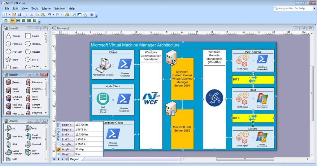
The current version of the above code is in the Git repository at this link: VisioPowershellv01.ps1.
Brief Summary and Next Steps
Therefore, the final result fully meets our expectations. Microsoft System Center Virtual Machine Manager 2007 architecture diagram was created using Powershell Code.
However, this approach has significant drawbacks.
The total size of this code is more than 500 lines. Therefore, the topic of the next publication is the optimization of this code using Powershell functions.
But that will be discussed in the next publication.
See you in a few days.
Sincerely, AIRRA!

