Wstęp
Witam wszystkich czytelników bloga o Architekturze IT i Edukacji.
Kontynuujemy publikację artykułów pod konceptualnym tytułem „Architektura i Design. Wdrażanie i eksploatacja. Kod i programowanie”.
W poprzednim artykule mówiliśmy ogólnie o tej koncepcji oraz o tworzeniu środowiska i konfigurowaniu narzędzi do tworzenia kodu.
Dzisiaj zaczniemy pisać kod wyświetlający diagram architektury systemu Microsoft System Center Virtual Machine Manager 2007 w formacie Visio dla powiązanej serii artykułów.
Microsoft Visio i PowerShell. Pierwsze kroki
Zacznijmy więc od prostych kroków.
Utwórzmy obiekt aplikacji Visio i nowy dokument na podstawie pustego szablonu. Ustawmy aktywną stronę, na której później programowo narysujemy nasz schemat architektoniczny.
# Step 1.
# Create Visio Object
# Create Document from Blank Template
# Set Active Page
$Application = New-Object -ComObject Visio.Application
$Application.Visible = $True
$Documents = $Application.Documents
$Document=$Application.Documents.Add('')
$Page=$Application.ActivePage
$Application.ActivePage.PageSheet
Dodajemy szablony podstawowych kształtów (BASIC_M.vss). Najpierw potrzebujemy szablonu prostokąta.
# Step 2.
# Add Basic Visio Stensils
# Set Masters Item Rectangle
$Stensil1 = $Application.Documents.Add("BASIC_M.vss")
$Rectangle = $Stensil1.Masters.Item("Rectangle")
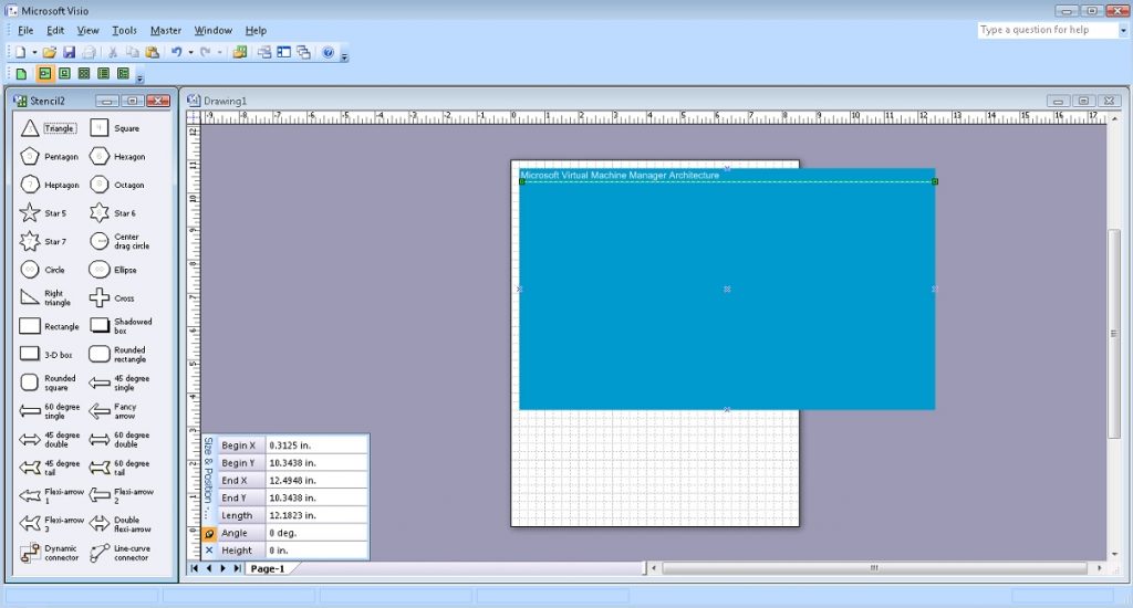
Rysujemy prostokąt z kolorem i napisem „Microsoft Virtual Machine Manager Architecture”. Tekst wyrównujemy wzdłuż górnej krawędzi prostokąta i do lewej. Ta liczba będzie podstawą naszego schematu. Aby estetycznie podkreślić napis, narysuj pod nim linię w odpowiednim kolorze.
# Step 3.
# Draw Main Rectangle, Set Size, Set Colour
# Set Text, Size, Color, Align
# Draw Line, Set Weight, Color
$Shape1 = $Page.Drop($Rectangle, 6.375, 7.125)
$Shape1.Cells('Width').Formula = '12.2501'
$Shape1.Cells('Height').Formula = '7.25'
$Shape1.Cells('FillForegnd').Formula = '=RGB(0,153,204)'
$Shape1.Cells('LinePattern').Formula = 0
$Shape1.Text = "Microsoft Virtual Machine Manager Architecture"
$Shape1.Cells('VerticalAlign') = 0
$Shape1.Cells('Para.HorzAlign') = 0
$Shape1.Cells('Char.Size').Formula = '20 pt'
$Shape1.Cells('Char.Color').Formula = '=RGB(255,255,255)'
$Line1 = $Page.DrawLine(0.3125, 10.3438, 12.4948, 10.3438)
$Line1.Cells('LineWeight').Formula = '1 pt'
$Line1.Cells('LineColor').Formula = '=RGB(255,255,255)'
Pośredni wynik poprzednich kroków wygląda tak:
Podobnie narysuj prostokąt, który będzie wyświetlał system klienta.
# Step 4.
# Draw Client Rectangle, Set Size, Set Colour
# Set Text, Align
# Draw Line
$Shape2 = $Page.Drop($Rectangle, 1.7656, 9.2344)
$Shape2.Cells('Width').Formula = '2.7813'
$Shape2.Cells('Height').Formula = '1.9688'
$Shape2.Cells('FillForegnd').Formula = '=RGB(209,235,241)'
$Shape2.Cells('LinePattern').Formula = 1
$Shape2.Text = "Client"
$Shape2.Cells('VerticalAlign') = 0
$Shape2.Cells('Char.Size').Formula = '14 pt'
$Line2 = $Page.DrawLine(0.4297, 9.9427, 3.0833, 9.9427)
$Line2.Cells('LineWeight').Formula = '0.5 pt'
$Line2.Cells('LineColor').Formula = '=RGB(0,0,0)'
W tym prostokącie będzie kilka obiektów. Dodamy szablony figur o tematyce komputerowej (COMPS_M.vss) i będziemy pracować z szablonem ikony komputera osobistego „PC”.
# Step 5.
# Add Computer Items Visio Stensils
# Set Masters item PC
$Stensil2 = $Application.Documents.Add("COMPS_M.vss")
$PC1 = $Stensil2.Masters.Item("PC")
Załączamy obraz Komputera Osobistego z podpisem „Konsola administratora”.
# Step 6.
# Draw item PC
# Set Text, Size
$Shape3 = $Page.Drop($PC1, 1.1173, 9.1693)
$Shape3.Text = "Administrator Console"
$Shape3.Cells('Char.Size').Formula = '10 pt'
Dodaj ikonę PowerShell. W takim przypadku wykorzystamy zdjęcie przygotowane wcześniej w formacie PNG (PowerShell.png).
# Step 7.
# Draw Powershell Icon
# Set Position, Size
# Set Text
$Picture1 = $Page.Import("c:\!\powershell.png")
$Picture1.Cells('Width').Formula = '0.9843'
$Picture1.Cells('Height').Formula = '0.9843'
$Picture1.Cells('PinX').Formula = '2.5547'
$Picture1.Cells('PinY').Formula = '9.2682'
$Picture1.Text = "Windows Powershell"
$Picture1.Cells('Char.Size').Formula = '10 pt'
Rysujemy prostokąt, który wyświetli programowy interfejs komunikacji między systemami klienckimi a systemami serwerowymi – Windows Communication Foundation.
# Step 8.
# Draw WCF Rectangle, Set Size, Set Colour
# Set Text, Align
# Draw Line
$Shape4 = $Page.Drop($Rectangle, 4.2682, 6.9063)
$Shape4.Cells('Width').Formula = '1.5'
$Shape4.Cells('Height').Formula = '6.625'
$Shape4.Cells('FillForegnd').Formula = '=RGB(255,255,255)'
$Shape4.Cells('LinePattern').Formula = 1
$Shape4.Text = "Windows Communication Foundation"
$Shape4.Cells('VerticalAlign') = 0
$Shape4.Cells('Char.Size').Formula = '14 pt'
$Line3 = $Page.DrawLine(3.5664, 9.4063, 4.9492, 9.4063)
$Line3.Cells('LineWeight').Formula = '0.5 pt'
$Line3.Cells('LineColor').Formula = '=RGB(0,0,0)'
Dodaj ikonę WCF.
# Step 9.
# Draw WCF Icon
# Set Position, Size
$Picture2 = $Page.Import("c:\!\WCF.png")
$Picture2.Cells('Width').Formula = '1.412'
$Picture2.Cells('Height').Formula = '1.0443'
$Picture2.Cells('PinX').Formula = '4.2708'
$Picture2.Cells('PinY').Formula = '6.9779'
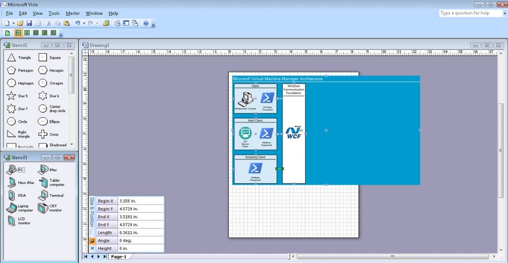
Łączymy linią dwa obiekty – System Klienta z interfejsem programowym Windows Communication Foundation. Będzie to odzwierciedlać komunikację dwukierunkową.
# Step 10.
# Draw Line communication from Client to WCF
# Set Arrow
$Line4 = $Page.DrawLine(3.1563, 9.2396, 3.5174, 9.2396)
$Line4.Cells('LineColor').Formula = '=RGB(255,255,255)'
$Line4.Cells('BeginArrow').Formula=4
$Line4.Cells('EndArrow').Formula=4
Dodaj prostokąt, który wyświetli klienta WWW.
# Step 11.
# Draw Web Client Rectangle, Set Size, Set Colour
# Set Text, Align
# Draw Line
$Shape5 = $Page.Drop($Rectangle, 1.7656, 6.8776)
$Shape5.Cells('Width').Formula = '2.7813'
$Shape5.Cells('Height').Formula = '2.1094'
$Shape5.Cells('FillForegnd').Formula = '=RGB(209,235,241)'
$Shape5.Cells('LinePattern').Formula = 1
$Shape5.Text = "Web Client"
$Shape5.Cells('VerticalAlign') = 0
$Shape5.Cells('Char.Size').Formula = '14 pt'
$Line5 = $Page.DrawLine(0.4297, 7.6562, 3.0833, 7.6562)
$Line5.Cells('LineWeight').Formula = '0.5 pt'
$Line5.Cells('LineColor').Formula = '=RGB(0,0,0)'
Podobnie jak w poprzednich krokach, dodajemy ikonę samoobsługowego portalu internetowego (SelfServicePortal.png) i kolejną ikonę PowerShell.
# Step 12.
# Draw Self Service Portal Icon
# Set Position, Size
# Set Text
$Picture3 = $Page.Import("c:\!\SelfServicePortal.png")
$Picture3.Cells('Width').Formula = '0.8438'
$Picture3.Cells('Height').Formula = '0.8438'
$Picture3.Cells('PinX').Formula = '1.1094'
$Picture3.Cells('PinY').Formula = '6.9271'
$Picture3.Text = "Self Service Portal"
$Picture3.Cells('Char.Size').Formula = '10 pt'
# Step 13.
# Draw Powershell Icon
# Set Position, Size
# Set Text
$Picture4 = $Page.Import("c:\!\powershell.png")
$Picture4.Cells('Width').Formula = '0.9843'
$Picture4.Cells('Height').Formula = '0.9843'
$Picture4.Cells('PinX').Formula = '2.4922'
$Picture4.Cells('PinY').Formula = '6.9192'
$Picture4.Text = "Windows Powershell"
$Picture4.Cells('Char.Size').Formula = '10 pt'Podobnie łączymy te dwa obiekty ponownie linią – Web Client z interfejsem oprogramowania Windows Communication Foundation. Odzwierciedla to również komunikację dwukierunkową.
# Step 14.
# Draw Line communication from Web Client to WCF
# Set Arrow
$Line6 = $Page.DrawLine(3.158, 6.8802, 3.5191, 6.8802)
$Line6.Cells('LineColor').Formula = '=RGB(255,255,255)'
$Line6.Cells('BeginArrow').Formula=4
$Line6.Cells('EndArrow').Formula=4
A uzupełnienie obrazu klienta to prostokąt przedstawiający klienta skryptów z inną ikoną PowerShell. I oczywiście łączymy ten obiekt z interfejsem oprogramowania Windows Communication Foundation za pomocą komunikacji dwukierunkowej.
# Step 15.
# Draw Scripting Client Rectangle, Set Size, Set Colour
# Set Text, Align
# Draw Line
$Shape6 = $Page.Drop($Rectangle, 1.7657, 4.5469)
$Shape6.Cells('Width').Formula = '2.7813'
$Shape6.Cells('Height').Formula = '1.9062'
$Shape6.Cells('FillForegnd').Formula = '=RGB(209,235,241)'
$Shape6.Cells('LinePattern').Formula = 1
$Shape6.Text = "Scripting Client"
$Shape6.Cells('VerticalAlign') = 0
$Shape6.Cells('Char.Size').Formula = '14 pt'
$Line7 = $Page.DrawLine(0.4297, 5.1979, 3.0834, 5.1979)
$Line7.Cells('LineWeight').Formula = '0.5 pt'
$Line7.Cells('LineColor').Formula = '=RGB(0,0,0)'
# Step 16.
# Draw Powershell Icon
# Set Position, Size
# Set Text
$Picture5 = $Page.Import("c:\!\powershell.png")
$Picture5.Cells('Width').Formula = '0.9843'
$Picture5.Cells('Height').Formula = '0.9843'
$Picture5.Cells('PinX').Formula = '1.7631'
$Picture5.Cells('PinY').Formula = '4.6015'
$Picture5.Text = "Windows Powershell"
$Picture5.Cells('Char.Size').Formula = '10 pt'# Step 17.
# Draw Line communication from Scripting Client to WCF
# Set Arrow
$Line8 = $Page.DrawLine(3.158, 4.5729, 3.5191, 4.5729)
$Line8.Cells('LineColor').Formula = '=RGB(255,255,255)'
$Line8.Cells('BeginArrow').Formula=4
$Line8.Cells('EndArrow').Formula=4Wynik poprzednich kroków wygląda tak:
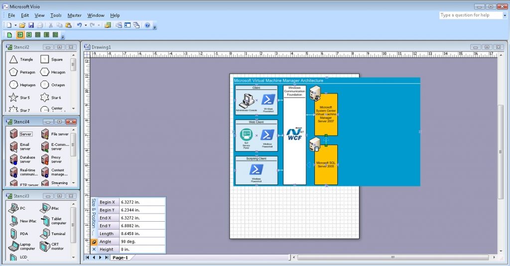
Przejdźmy teraz do głównych usług. Do wizualizacji pracy części serwerowej użyjemy szablonów rycin o odpowiednim temacie (SERVER_M.vss) oraz będziemy pracować z szablonami ikon Management Server „Management server” oraz Database Server „Database server” . Najpierw rysujemy prostokąt do wizualizacji Microsoft System Center Virtual Machine Manager Server 2007 i odpowiednio inny dla Microsoft SQL Server 2005. Umieszczamy odpowiednie ikony serwerów na górze prostokątów w lewym górnym rogu. I oczywiście łączymy obiekt „Microsoft System Center Virtual Machine Manager Server 2007” z interfejsem oprogramowania Windows Communication Foundation za pomocą komunikacji dwukierunkowej, a z Microsoft SQL Server 2005 za pomocą komunikacji jednokierunkowej.
# Step 18.
# Draw Microsoft System Center
# Virtual Machine Manager Server 2007 Rectangle
# Set Size, Set Colour
# Set Text, Align
$Shape7 = $Page.Drop($Rectangle, 6.3281, 8.2812)
$Shape7.Cells('Width').Formula = '1.5'
$Shape7.Cells('Height').Formula = '2.8125'
$Shape7.Cells('FillForegnd').Formula = '=RGB(255,192,0)'
$Shape7.Cells('LinePattern').Formula = 1
$Shape7.Text = "Microsoft System Center Virtual Machine Manager Server 2007"
$Shape7.Cells('Char.Size').Formula = '14 pt'
# Step 19.
# Draw Microsoft SQL Server 2005 Rectangle
# Set Size, Set Colour
# Set Text, Align
$Shape8 = $Page.Drop($Rectangle, 6.3281, 4.9219)
$Shape8.Cells('Width').Formula = '1.5'
$Shape8.Cells('Height').Formula = '2.6563'
$Shape8.Cells('FillForegnd').Formula = '=RGB(255,192,0)'
$Shape8.Cells('LinePattern').Formula = 1
$Shape8.Text = "Microsoft SQL Server 2005"
$Shape8.Cells('Char.Size').Formula = '14 pt'# Step 20.
# Add Server Items Visio Stensils
# Set Masters item Management Server and Database Server
$Stensil3 = $Application.Documents.Add("SERVER_M.vss")
$MS1 = $Stensil3.Masters.Item("Management server")
$DBS1 = $Stensil3.Masters.Item("Database server")# Step 21.
# Draw item Management Server
$Shape9 = $Page.Drop($MS1, 5.6043, 9.7421)# Step 22.
# Draw item Management Server
$Shape10 = $Page.Drop($DBS1, 5.5832, 6.3046)# Step 23.
# Draw Line communication from WCF to Microsoft System Center
# Virtual Machine Manager Server 2007
# Set Arrow
$Line9 = $Page.DrawLine(5.0052, 8.2604, 5.6024, 8.2604)
$Line9.Cells('LineColor').Formula = '=RGB(255,255,255)'
$Line9.Cells('BeginArrow').Formula=4
$Line9.Cells('EndArrow').Formula=4# Step 24.
# Draw Line communication from Microsoft System Center
# Virtual Machine Manager Server 2007 to Microsoft SQL Server 2005
# Set Arrow
$Line10 = $Page.DrawLine(6.3272, 6.2344, 6.3272, 6.8802)
$Line10.Cells('LineColor').Formula = '=RGB(255,255,255)'
$Line10.Cells('BeginArrow').Formula=4
$Line10.Cells('EndArrow').Formula=0Wynik poprzednich kroków wygląda tak:
Microsoft System Center Virtual Machine Manager Server 2007 współdziała z systemami agentów przy użyciu technologii Windows Remote Management (Win-RM). Narysujmy więc ten składnik architektury w taki sam sposób, w jaki narysowaliśmy wyświetlanie interfejsu oprogramowania Windows Communication Foundation. I połączmy ten komponent z obiektem Microsoft System Center Virtual Machine Manager Server 2007 za pomocą komunikacji dwukierunkowej.
# Step 25.
# Draw Win-RM Rectangle, Set Size, Set Colour
# Set Text, Align
# Draw Line
$Shape11 = $Page.Drop($Rectangle, 8.4375, 6.9219)
$Shape11.Cells('Width').Formula = '1.5'
$Shape11.Cells('Height').Formula = '6.6563'
$Shape11.Cells('FillForegnd').Formula = '=RGB(255,255,255)'
$Shape11.Cells('LinePattern').Formula = 1
$Shape11.Text = "Windows Remote Managemet (Win-RM)"
$Shape11.Cells('VerticalAlign') = 0
$Shape11.Cells('Char.Size').Formula = '14 pt'
$Line11 = $Page.DrawLine(7.75, 9.1875, 9.1328, 9.1875)
$Line11.Cells('LineWeight').Formula = '0.5 pt'
$Line11.Cells('LineColor').Formula = '=RGB(0,0,0)'
# Step 26.
# Draw Win-RM Icon
# Set Position, Size
$Picture6 = $Page.Import("c:\!\Win-RM.png")
$Picture6.Cells('Width').Formula = '1.1563'
$Picture6.Cells('Height').Formula = '1.1563'
$Picture6.Cells('PinX').Formula = '8.4293'
$Picture6.Cells('PinY').Formula = '7'# Step 27.
# Draw Line communication from Win-RM to Microsoft System Center
# Virtual Machine Manager Server 2007
# Set Arrow
$Line12 = $Page.DrawLine(7.0781, 8.2812, 7.6753, 8.2812)
$Line12.Cells('LineColor').Formula = '=RGB(255,255,255)'
$Line12.Cells('BeginArrow').Formula=4
$Line12.Cells('EndArrow').Formula=4Interakcja z hostami wirtualizacji, biblioteką itp. oparta jest na VMM Agent. Zacznijmy wyświetlać te komponenty architektury od wizualizacji interakcji procesów migracji usług ze środowiska fizycznego do wirtualnego: Źródło P2V. Będziemy potrzebować prostokąta, linii, ikon VMM Agent i Powershell. I oczywiście wyświetlaj dwukierunkową komunikację dzięki technologii Windows Remote Managemet (Win-RM).
# Step 28.
# Draw P2V Source Rectangle, Set Size, Set Colour
# Set Text, Align
# Draw Line
$Shape12 = $Page.Drop($Rectangle, 10.9844, 9.5)
$Shape12.Cells('Width').Formula = '2.7813'
$Shape12.Cells('Height').Formula = '1.5'
$Shape12.Cells('FillForegnd').Formula = '=RGB(209,235,241)'
$Shape12.Cells('LinePattern').Formula = 1
$Shape12.Text = "P2V Source"
$Shape12.Cells('VerticalAlign') = 0
$Shape12.Cells('Char.Size').Formula = '14 pt'
$Line13 = $Page.DrawLine(9.6485, 9.9739, 12.3021, 9.9739)
$Line13.Cells('LineWeight').Formula = '0.5 pt'
$Line13.Cells('LineColor').Formula = '=RGB(0,0,0)'
# Step 29.
# Draw VMM Agent Icon
# Set Position, Size
# Set Text
$Picture7 = $Page.Import("c:\!\VMMAgent.png")
$Picture7.Cells('Width').Formula = '0.8438'
$Picture7.Cells('Height').Formula = '0.8438'
$Picture7.Cells('PinX').Formula = '10.2969'
$Picture7.Cells('PinY').Formula = '9.5'
$Picture7.Text = "VMM Agent"
$Picture7.Cells('Char.Size').Formula = '10 pt'# Step 30.
# Draw Powershell Icon
# Set Position, Size
# Set Text
$Picture8 = $Page.Import("c:\!\powershell.png")
$Picture8.Cells('Width').Formula = '0.7968'
$Picture8.Cells('Height').Formula = '0.7968'
$Picture8.Cells('PinX').Formula = '11.6016'
$Picture8.Cells('PinY').Formula = '9.6016'
$Picture8.Text = "Windows Powershell"
$Picture8.Cells('Char.Size').Formula = '10 pt'# Step 31.
# Draw Line communication from P2V Source to Win-RM
# Set Arrow
$Line14 = $Page.DrawLine(9.1875, 9.487, 9.599, 9.487)
$Line14.Cells('LineColor').Formula = '=RGB(255,255,255)'
$Line14.Cells('BeginArrow').Formula=4
$Line14.Cells('EndArrow').Formula=4Podobnie wyświetlamy Hosty wirtualizacji – Microsoft Virtual Server 2005 R2.
# Step 32.
# Draw Host Rectangle, Set Size, Set Colour
# Set Text, Align
# Draw Line
$Shape13 = $Page.Drop($Rectangle, 10.9792, 6.9427)
$Shape13.Cells('Width').Formula = '2.7813'
$Shape13.Cells('Height').Formula = '1.5'
$Shape13.Cells('FillForegnd').Formula = '=RGB(209,235,241)'
$Shape13.Cells('LinePattern').Formula = 1
$Shape13.Text = "Host"
$Shape13.Cells('VerticalAlign') = 0
$Shape13.Cells('Char.Size').Formula = '14 pt'
$Line15 = $Page.DrawLine(9.6472, 7.4219, 12.3008, 7.4219)
$Line15.Cells('LineWeight').Formula = '0.5 pt'
$Line15.Cells('LineColor').Formula = '=RGB(0,0,0)'
# Step 33.
# Draw VMM Agent Icon
# Set Position, Size
# Set Text
$Picture9 = $Page.Import("c:\!\VMMAgent.png")
$Picture9.Cells('Width').Formula = '0.8438'
$Picture9.Cells('Height').Formula = '0.8438'
$Picture9.Cells('PinX').Formula = '10.2917'
$Picture9.Cells('PinY').Formula = '6.9427'
$Picture9.Text = "VMM Agent"
$Picture9.Cells('Char.Size').Formula = '10 pt'# Step 34.
# Draw Microsoft Virtual Server 2005 R2 Icon
# Set Position, Size
# Set Text
$Picture10 = $Page.Import("c:\!\WS.jpg")
$Picture10.Cells('Width').Formula = '0.8125'
$Picture10.Cells('Height').Formula = '0.7404'
$Picture10.Cells('PinX').Formula = '11.5938'
$Picture10.Cells('PinY').Formula = '6.9423'
$Picture10.Text = "Microsoft Virtual Server 2005 R2"
$Picture10.Cells('Char.Size').Formula = '7 pt'# Step 35.
# Draw Line communication from Host to Win-RM
# Set Arrow
$Line16 = $Page.DrawLine(9.1849, 6.941, 9.5964, 6.941)
$Line16.Cells('LineColor').Formula = '=RGB(255,255,255)'
$Line16.Cells('BeginArrow').Formula=4
$Line16.Cells('EndArrow').Formula=4I podobnie jak w poprzednich krokach wyświetlamy elementy Biblioteki.
# Step 36.
# Draw Library Rectangle, Set Size, Set Colour
# Set Text, Align
# Draw Line
$Shape14 = $Page.Drop($Rectangle, 10.9792, 4.3542)
$Shape14.Cells('Width').Formula = '2.7813'
$Shape14.Cells('Height').Formula = '1.5'
$Shape14.Cells('FillForegnd').Formula = '=RGB(209,235,241)'
$Shape14.Cells('LinePattern').Formula = 1
$Shape14.Text = "Library"
$Shape14.Cells('VerticalAlign') = 0
$Shape14.Cells('Char.Size').Formula = '14 pt'
$Line17 = $Page.DrawLine(9.6419, 4.8073, 12.2955, 4.8073)
$Line17.Cells('LineWeight').Formula = '0.5 pt'
$Line17.Cells('LineColor').Formula = '=RGB(0,0,0)'
# Step 37.
# Draw VMM Agent Icon
# Set Position, Size
# Set Text
$Picture11 = $Page.Import("c:\!\VMMAgent.png")
$Picture11.Cells('Width').Formula = '0.8438'
$Picture11.Cells('Height').Formula = '0.8438'
$Picture11.Cells('PinX').Formula = '10.2917'
$Picture11.Cells('PinY').Formula = '4.3542'
$Picture11.Text = "VMM Agent"
$Picture11.Cells('Char.Size').Formula = '10 pt'# Step 38.
# Draw Windows Server 2003 R2 Icon
# Set Position, Size
# Set Text
$Picture12 = $Page.Import("c:\!\WS.jpg")
$Picture12.Cells('Width').Formula = '0.8125'
$Picture12.Cells('Height').Formula = '0.7404'
$Picture12.Cells('PinX').Formula = '11.5625'
$Picture12.Cells('PinY').Formula = '4.3702'
$Picture12.Text = "Windows Server 2003 R2"
$Picture12.Cells('Char.Size').Formula = '7 pt'# Step 39.
# Draw Line communication from Library to Win-RM
# Set Arrow
$Line18 = $Page.DrawLine(9.1901, 4.3611, 9.6016, 4.3611)
$Line18.Cells('LineColor').Formula = '=RGB(255,255,255)'
$Line18.Cells('BeginArrow').Formula=4
$Line18.Cells('EndArrow').Formula=4Wynik poprzednich kroków wygląda tak:
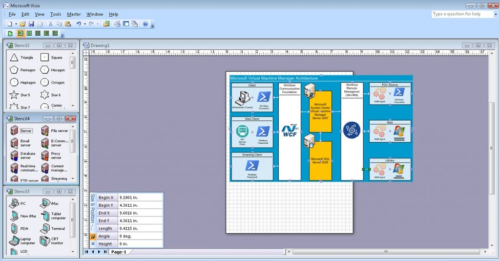
Interakcja pomiędzy Hostami Wirtualizacji, Biblioteką i procesami migracji usług ze środowiska fizycznego do wirtualnego: Źródło P2V odbywa się z wykorzystaniem technologii Inteligentnego Transferu w Tle (BITS). Pokażemy tę dwukierunkową interakcję pomiędzy końcowymi elementami architektury.
# Step 40.
# Draw BITS Rectangle, Set Size, Set Colour
# Set Text, Align
# Draw Line
$Shape15 = $Page.Drop($Rectangle, 10.9844, 8.2292)
$Shape15.Cells('Width').Formula = '2.75'
$Shape15.Cells('Height').Formula = '0.5625'
$Shape15.Cells('FillForegnd').Formula = '=RGB(255,255,0)'
$Shape15.Cells('LinePattern').Formula = 1
$Shape15.Text = "BITS"
$Shape15.Cells('Para.HorzAlign') = 0
$Shape15.Cells('Char.Size').Formula = '14 pt'
# Step 41.
# Draw BITS Icon
# Set Position, Size
# Set Text
$Picture13 = $Page.Import("c:\!\BITS.jpg")
$Picture13.Cells('Width').Formula = '0.5417'
$Picture13.Cells('Height').Formula = '0.5417'
$Picture13.Cells('PinX').Formula = '10.974'
$Picture13.Cells('PinY').Formula = '8.2344'# Step 42.
# Draw Line communication from BITS to P2V Source
# Set Arrow
$Line19 = $Page.DrawLine(10.9844, 8.5104, 10.9844, 8.75)
$Line19.Cells('LineColor').Formula = '=RGB(255,255,255)'
$Line19.Cells('BeginArrow').Formula=4
$Line19.Cells('EndArrow').Formula=4# Step 43.
# Draw Line communication from BITS to Host
# Set Arrow
$Line20 = $Page.DrawLine(10.9844, 7.6849, 10.9844, 7.9219)
$Line20.Cells('LineColor').Formula = '=RGB(255,255,255)'
$Line20.Cells('BeginArrow').Formula=4
$Line20.Cells('EndArrow').Formula=4# Step 44.
# Draw BITS Rectangle, Set Size, Set Colour
# Set Text, Align
# Draw Line
$Shape16 = $Page.Drop($Rectangle, 10.9844, 5.6555)
$Shape16.Cells('Width').Formula = '2.75'
$Shape16.Cells('Height').Formula = '0.5625'
$Shape16.Cells('FillForegnd').Formula = '=RGB(255,255,0)'
$Shape16.Cells('LinePattern').Formula = 1
$Shape16.Text = "BITS"
$Shape16.Cells('Para.HorzAlign') = 0
$Shape16.Cells('Char.Size').Formula = '14 pt'# Step 45.
# Draw BITS Icon
# Set Position, Size
# Set Text
$Picture14 = $Page.Import("c:\!\BITS.jpg")
$Picture14.Cells('Width').Formula = '0.5417'
$Picture14.Cells('Height').Formula = '0.5417'
$Picture14.Cells('PinX').Formula = '10.974'
$Picture14.Cells('PinY').Formula = '5.6607'# Step 46.
# Draw Line communication from BITS to Host
# Set Arrow
$Line21 = $Page.DrawLine(10.9844, 5.9245, 10.9844, 6.1901)
$Line21.Cells('LineColor').Formula = '=RGB(255,255,255)'
$Line21.Cells('BeginArrow').Formula=4
$Line21.Cells('EndArrow').Formula=4# Step 47.
# Draw Line communication from BITS to Library
# Set Arrow
$Line22 = $Page.DrawLine(10.9792, 5.1042, 10.9792, 5.375)
$Line22.Cells('LineColor').Formula = '=RGB(255,255,255)'
$Line22.Cells('BeginArrow').Formula=4
$Line22.Cells('EndArrow').Formula=4Na koniec zmienimy rozmiar strony zgodnie z wymiarami naszego diagramu, zapiszemy jako plik na dysku i zamkniemy aplikację Visio.
# Step 48.
# Resise Page To Fit Contents
$Page.ResizeToFitContents()
# Step 49.
# Save Document
# And Quit Application
$Document.SaveAs(“C:\!\MsSCVMM2007Arch.vsd”)
$Application.Quit()Ostateczny wynik schematu pokazano na rysunku.
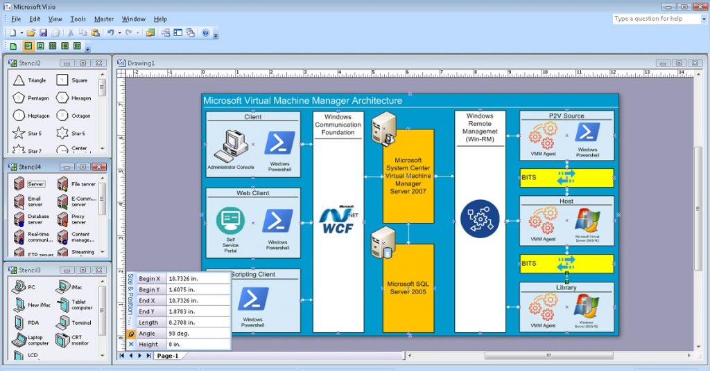
Aktualna wersja powyższego kodu znajduje się w repozytorium Git pod tym linkiem: VisioPowershellv01.ps1.
Krótkie podsumowanie i Kolejne kroki
Dlatego efekt końcowy w pełni spełnia nasze oczekiwania. Przy pomocy kodu Powershell powstał schemat architektury systemu Microsoft System Center Virtual Machine Manager 2007.
Podejście to ma jednak istotne wady.
Całkowita objętość tego kodu to ponad 500 wierszy. Dlatego tematem kolejnego wpisu jest optymalizacja tego kodu za pomocą funkcji Powershell.
Ale to zostanie omówione w następnej publikacji.
Do zobaczenia za kilka dni.
Z poważaniem, AIRRA!

